 ɨһɨ���ֻ����
- ������G1206SL3210-1PE32-1UL0����ģ��
��ϸ��Ϣ
�ͺ�������ģ�� Ʒ����������G120 �ӹ��������� ֧��������1 �������1 Ƶ��������1 ����������1 ���γߴ���5 mm Ӧ���������Զ����� ������G1206SL3210-1PE32-1UL0����ģ�� 6SL3210-1PE32-1UL0
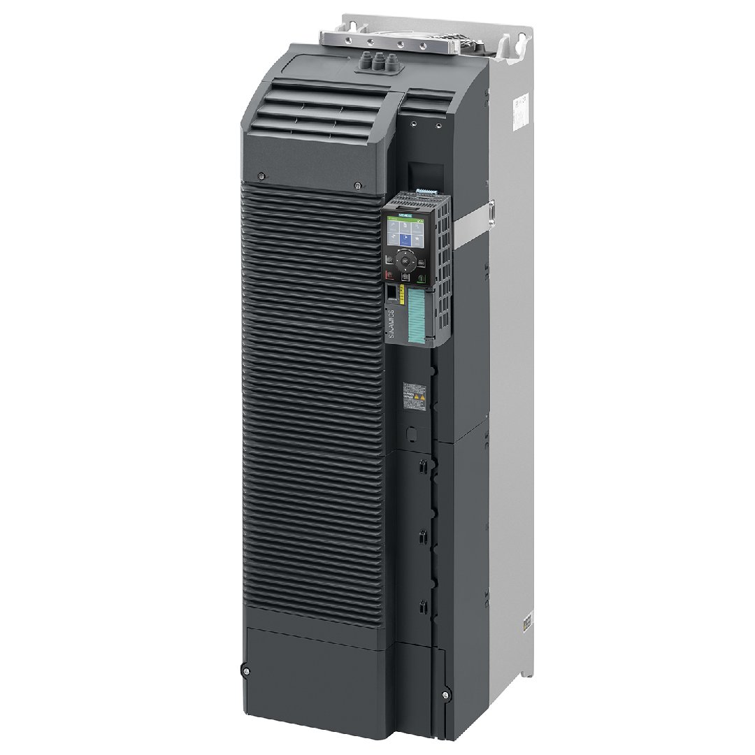
SINAMICS G120 ����ģ�� PM 240-2 δ���� ������ʽ�ƶ�ն���� 380-480V+10/-20% ���ཻ�� 47-63Hz �ع��ع��ʣ�90kW �� 200% 3S��150% 57S�� 100% 240S�������¶� -20 �� +50°C(HO);���� ����أ�110kW �� 150% 3S��110% 57S�� 100% 240S�������¶� -20 �� +40°C(LO) 708x 305x 357����x��x�,FSF �����ȼ� IP20 �������Ƶ�Ԫ�� ������Ԫ ���� CU �̼�- �汾 V4.7 HF8
����
SINAMICS G120C, frame sizes FSAA to FSF, with Intelligent Operator Panel IOP‑2
SINAMICS G120C compact converters offer a well-balanced combination of features to address a wide range of applications. They are compact, rugged devices that are easy to operate and can be optionally equipped with a basic or advanced operator panel.
SINAMICS G120C converters are especially suitable when it comes to meeting the requirements of system integrators, OEMs and distributors regarding high productivity and tailored performance.
����
- Compact design
- Frame size FSAA allows easy DIN rail mounting
- Side-by-side design
- High power density, low envelope dimensions
- Simple installation in the tightest space
- Low space requirement
- Use in small control cabinets, close to the machine
- Optimized parameter set
- Optimized commissioning
- Compact Operating Instructions
- BOP‑2 or IOP‑2 Operator Panels can be used
- Integrated USB connection
- Simple and fast software parameter assignment
- Simple to use during commissioning and in operation
- Minimized training costs, existing SINAMICS know-how can be used
- High degree of service friendliness, simple maintenance
- Plug-in terminals
- Cloning function using BOP‑2, IOP‑2, or memory card
- Operating hours counter for "drive on" and "motor on"
- Fast mechanical installation
- Intuitive standard commissioning
- Component of Totally Integrated Automation
- Energy-efficient, sensorless vector control
- Automatic flux reduction with V/f ECO
- Integrated energy saving computer
- Safety Integrated (STO)
- Communication versions with PROFINET / EtherNet/IP, PROFIBUS DP, USS/Modbus RTU
- Wireless commissioning, operation and diagnostics via mobile device or laptop thanks to the optional SINAMICS G120 Smart Access
- Connection to the Cloud MindSphere with the optionally available SINAMICS CONNECT 300 IoT Gateway
- Varnished modules
- Operation up to an ambient temperature of 60 °C
Extended warranty
For SINAMICS G120C, Siemens offers an optional extension of warranty up to 5½ years via Service Protect:
- Free for the first 6 months after registering the product at:
https://myregistration.siemens.com - With costs for 3 or 5 additional years
More information is available at:
https://support.industry.siemens.com/cs/ww/en/sc/4842Concerning standard warranty please ask your partner at Siemens. Your partner can be found in our Personal Contacts Database at:
www.siemens.com/automation-contact
���
SINAMICS G120C is a compact converter for control cabinet mounting in IP20 degree of protection where the Control Unit (CU) and Power Module (PM) function units are combined in one device.
The compact mechanical design and the high power density allow these devices to be installed in machine control enclosures and control cabinets for maximum space utilization. The SINAMICS G120C compact converter can be butt-mounted directly, without derating at temperatures up to 40 °C (104 °F).
SINAMICS G120C, frame size FSAA with BOP-2
SINAMICS G120C can be integrated into the widest range of applications, either using the integrated digital and analog inputs or via the integrated fieldbus interface (available in USS, Modbus RTU, PROFIBUS, PROFINET, EtherNet/IP versions). Especially the product versions with integrated PROFIBUS/PROFINET interface make full integration into the Siemens TIA family possible, therefore allowing the advantages of the seamless TIA product family to be fully utilized. SINAMICS G120C devices are preset in the factory so that they can be immediately connected to PROFIBUS or PROFINET fieldbus systems without parameterization.
Wireless commissioning, operation and diagnostics via mobile device or laptop thanks to the optional web server module SINAMICS G120 Smart Access enabling user-friendly operation and easy access to the converter, even if this is installed in areas difficult to access.
With the optionally available SINAMICS CONNECT 300 IoT Gateway, connection to the Cloud MindSphere is possible.
SINAMICS G120C is also equipped with the safety function STO (Safe Torque Off) as standard, which is used to safely stop drives. As a consequence, machine manufacturers can simply comply with current machinery directives with minimum associated costs.
SINAMICS G120C can control asynchronous (induction) motors in the power range from 0.37 kW up to 132 kW (0.5 hp to 200 hp). Reliable and efficient motor operation is achieved by using state-of-the-art IGBT technology combined with vector control. The extensive range of functions integrated in the SINAMICS G120C also offers a high degree of protection for the converter and motor.
Line-side components
Line filter
SINAMICS G120C can be ordered with or without integrated Class A line filters. Optionally, an external Class B line filter can be used for classifying in a higher interference class.
Line reactors
Line reactors smooth the current drawn by the converter and thus reduce harmonic components in the line current. Through the reduction of the current harmonics, the thermal load on the power components in the rectifier and in the DC link capacitors is reduced as well as the harmonic effects on the supply. The use of a line reactor increases the service life of the converter. A DC link reactor is integrated in frame sizes FSD to FSF, and therefore no line reactor is required.
Recommended line-side overcurrent protection devices
Overcurrent protection devices are absolutely necessary for the operation of the converters. The table listed in the section "Recommended line-side overcurrent protection devices" provides recommendations according to IEC and UL regulations, depending on the area of application. Recommendations on further overcurrent protection devices are available at:
https://support.industry.siemens.com/cs/document/109750343More information about the listed Siemens fuses is available in Catalog LV 10 as well as in the Industry Mall.
DC link components
Braking resistors
Excess energy in the DC link is dissipated in the braking resistor. The braking resistors are designed for use with the SINAMICS G120C. This has an integrated braking chopper (electronic switch). For the electromagnetically compatible connection of an optionally connectable braking resistor, the corresponding shield connection kit is to be ordered for frame sizes FSD to FSF.
Load-side power components
Output reactors
Output reactors reduce the rate of voltage rise (dv/dt) and the height of the current peaks, and enable longer motor cables to be connected.
Supplementary system components
IOP‑2 Intelligent Operator Panel
Graphics-based, user-friendly and powerful operator panel for commissioning and diagnostics as well as local operator control and monitoring of SINAMICS G120C.
BOP‑2 Basic Operator Panel
A 2-line display to provide support when commissioning and troubleshooting the drive. The drive can be locally controlled.
Memory card
The parameter settings for a converter can be stored on the SINAMICS SD memory card. When service is required, e.g. after the converter has been replaced and the data have been downloaded from the memory card, the drive system is immediately ready for use again. The associated memory card holder is integrated in the converter.
SINAMICS G120 Smart Access
Wireless commissioning, operation and diagnostics via mobile device or laptop thanks to the optional web server module SINAMICS G120 Smart Access enabling user-friendly operation and easy access to the converter, even if this is installed in areas difficult to access.
SINAMICS CONNECT 300 IoT Gateway
Connection to the Cloud MindSphere with the optionally available SINAMICS CONNECT 300 IoT Gateway.
PC converter connection kit 2
For controlling and commissioning a converter directly from a PC if the STARTER commissioning tool or SINAMICS Startdrive has been installed on the PC.
Shield connection kits
A shield connection kit is included in the scope of delivery for frame sizes FSAA to FSC.
A set of shield plates is included in the scope of delivery for the motor and signal cables corresponding to the frame size for the frame sizes FSD to FSF. For the electromagnetically compatible connection of an optionally connectable braking resistor, the corresponding shield connection kit is to be ordered for frame sizes FSD to FSF.Additional options
Further selected accessories are available from "Siemens Product Partner for Drives Options": http://www.siemens.com/drives-options-partner
Spare parts
Shield connection kits
A shield connection kit is supplied as standard with frame sizes FSAA to FSC. These shield connection kits can also be ordered as spare parts.
A set of shield plates is included in the scope of delivery for the motor and signal cables corresponding to the frame size for the frame sizes FSD to FSF. For the electromagnetically compatible connection of an optionally connectable braking resistor, the corresponding shield connection kit is to be ordered for frame sizes FSD to FSF.Spare parts kit
This kit comprises four I/O terminals, one RS485 terminal, two pairs of Control Unit doors (1 × PN and 1 × other communication versions) and one blanking cover.
Set of connectors
A set of connectors for the line feeder cable, braking resistor and motor cable can be ordered corresponding to the frame size of the SINAMICS G120C converter.
Roof-mounted fan
A roof-mounted fan (at the top of the device) comprising a pre-assembled unit with holder and fan can be ordered corresponding to the frame size of the SINAMICS G120C.
Fan unit
A replacement fan (at the rear of the device; heat sink) comprising a pre-assembled unit with holder and fan can be ordered corresponding to the frame size of the SINAMICS G120C.
����
Connection example for SINAMICS G120C
USS/Modbus RTU communication interface
PROFIBUS DP communication interface
PROFINET, EtherNet/IP communication interface
Available optional power and DC link components
The following line-side components, DC link components and load-side power components are optionally available in the appropriate frames sizes:
Frame size
FSAA, FSA
FSB
FSC
FSD
FSE
FSF
Line-side components
Line filter class A
F
F
F
F
F
F
Line filter class B
U
U
U
–
–
–
Line reactor
S 1)
S
S
I
I
I
DC link components
Braking resistor
S 1)
S
S
S
S
S
Load-side power components
Output reactor
S 1)
S
S
S
S
S
U = Base component
S = Lateral mounting
I = Integrated
F = Converter available with and without integrated filter class A
– = Not possible
1) Line reactors, braking resistors and output reactors that are suitable for base mounting are also available for SINAMICS G120C, frame size FSAA, 0.55 kW to 2.2 kW. For 2.2 kW, operation of the line reactor, braking resistor and output reactor that are suitable for base mounting is only permitted for operating the converter with rated power of 1.5 kW based on high overload (HO).
More information is available in the operating instructions on the Internet at:
www.siemens.com/sinamics-g120c/documentationMaximum permissible cable lengths from the motor to the converter when using output reactors or line filters
The following load-side power components are optionally available in the appropriate frame sizes and result in the following maximum cable lengths, if necessary in combination with line filters for complying with EMC requirements:
Maximum permissible motor cable lengths (shielded/unshielded) in m (ft)
FSAA
FSA
FSB
FSC
FSD
FSE
FSF
Without optional power components
- Versions without integrated line filter
150 1)/150 (492 1))/492)
150/150 (492/492)
150/150 (492/492)
150/150 (492/492)
200/300 (656/984)
200/300 (656/984)
300/450 (984/1476)
- Versions with integrated line filter class A
50/100 (164/328)
50/100 (164/328)
50/100 (164/328)
50/100 (164/328)
200/300 (656/984)
200/300 (656/984)
300/450 (984/1476)
With optional output reactor
- At 380 ... 415 V 3 AC
150/225 (492/738)
150/225 (492/738)
150/225 (492/738)
150/225 (492/738)
200/300 (656/984) 4)
200/300 (656/984) 4)
300/450 (984/1476) 4)
- At 440 ... 480 V 3 AC
100/150 (328/492)
100/150 (328/492)
100/150 (328/492)
100/150 (328/492)
200/300 (656/984) 4)
200/300 (656/984) 4)
300/450 (984/1476) 4)
With integrated line filter class A
According to EN 55011 to comply with radio interference emissions according to EN 61800‑3 EMC Category C2
25 2)/– (82 2))/–)
25 2)/– (82 2))/–)
25 2)/– (82 2))/–)
25 3)/– (82 3))/–)
150/– (492/–)
150/– (492/–)
150/– (492/–)
With optional, external line filter class B
According to EN 55011 to comply with cable-conducted radio interference emissions according to EN 61800‑3 EMC Category C1 5), together with versions without integrated line filters
50/– (164/–)
25/– (82/–)
50/– (164/–)
50/– (164/–)
–
–
–
With optional, external line filter class B
According to EN 55011 and output reactor to comply with radio interference emissions according to EN 61800‑3 EMC Category C2 5), together with versions without integrated line filters
- At 380 ... 415 V 3 AC
150/– (492/–)
150/– (492/–)
150/– (492/–)
150/– (492/–)
–
–
–
- At 440 ... 480 V 3 AC
100/– (328/–)
100/– (328/–)
100/– (328/–)
100/– (328/–)
–
–
–
1) For SINAMICS G120C frame size FSAA 2.2 kW with low-capacitance CY cable 150 m (492 ft) (shielded) – otherwise 125 m (410 ft) (shielded).
2) With low-capacitance CY cable 50 m (164 ft) (shielded).
3) With low-capacitance CY cable 100 m (328 ft) (shielded).
4) For frame sizes FSD to FSF the maximum permissible cable lengths are not increased with an output reactor. By means of the output reactor, the loading of the motor windings is reduced by lower rates of voltage rise (dv/dt). By means of two output reactors connected in series, the maximum permissible cable lengths for frame sizes FSD and FSE are increased to 350 m (1148 ft) (shielded) and 525 m (1723 ft) (unshielded), and for frame size FSF to 525 m (1723 ft) (shielded) and 800 m (2625 ft) (unshielded).
5) More information is available in the operating instructions on the Internet at:
www.siemens.com/sinamics-g120c/documentation
��̬
The following electronic configuring aids and engineering tools are available for SINAMICS G120C compact converters:
Drive Technology Configurator (DT Configurator)
The Drive Technology Configurator (DT Configurator) helps you to configure the optimum drive technology products for a number of applications – starting with gearboxes, motors, converters as well as the associated options and components and ending with controllers, software licenses and connection systems.
The DT Configurator can be used on the internet without requiring any installation. The DT Configurator can be found in the Siemens Industry Mall at the following address:
www.siemens.com/dt-configuratorSIZER for Siemens Drives (integrated in the TIA Selection Tool) engineering tool
The SIZER for Siemens Drives engineering tool makes it easy to configure the SINAMICS converter family. It provides support when selecting the hardware and firmware components necessary to implement a drive task. SIZER for Siemens Drives is designed to support configuring of the entire drive system.
You can find more information on the SIZER for Siemens Drives engineering tool in the Engineering tools section.
The SIZER for Siemens Drives engineering tool is available free on the internet at:
www.siemens.com/sizerSTARTER commissioning tool
The STARTER commissioning tool allows menu-prompted commissioning, optimization and diagnostics and the TIA functionality. Apart from the SINAMICS drives, STARTER is also suitable for MICROMASTER 4 devices.
You can find more information on the STARTER commissioning tool in the Engineering tools section.
More information about the STARTER commissioning tool is available on the internet at
www.siemens.com/starterSINAMICS Startdrive commissioning tool
SINAMICS Startdrive is a tool integrated into the TIA Portal for configuring, commissioning and diagnostics of the SINAMICS converter family. SINAMICS Startdrive (V16 update 4 and higher) can be used to implement converter tasks with most of the SINAMICS G and SINAMICS S converter series. The commissioning tool has been optimized in terms of simplicity, ease of use, and consistent use of the benefits of the TIA Portal to provide a uniform working environment for PLC, HMI and drives.
You can find more information on the SINAMICS Startdrive commissioning tool in the Engineering tools section.
The SINAMICS Startdrive commissioning tool is available for free on the internet at:
www.siemens.com/startdriveDrive ES engineering system
Drive ES is the engineering system that can be used to integrate the communication, configuration and data management functions of Siemens drive technology into the SIMATIC automation world easily, efficiently and cost-effectively. The Drive ES PCS software package is available for SINAMICS.
You can find more information on the Drive ES engineering system in the Engineering tools section.
More information about the Drive ES engineering system is available on the internet at
www.siemens.com/drive-es
�����淶
Unless explicitly specified otherwise, the following technical specifications are valid for all SINAMICS G120C compact converters.
General technical specifications
Mechanical specifications
Vibratory load
- Transport acc. to IEC 60721‑3‑2: 1997 1)
Class 2M3
- Operation acc. to IEC 60721‑3‑3: 2002
Class 3M1
Shock load
- Transport acc. to IEC 60721‑3‑2: 1997 1)
Class 2M3
- Operation acc. to IEC 60721‑3‑3: 2002
Class 3M2
Degree of protection
IP20/ UL Open Type
Permissible mounting position
Vertical wall mounting
Ambient conditions
External 24 V supply
according to IEC 60204-1
Contact-safe SELV or PELV power supply.
The supply voltage must not exceed 60 V DC under single fault conditions.Protection class
according to IEC 61800-5-1
Class I (with protective grounding conductor)
Air humidity, max.
95 % at 40 °C (104 °F), condensation and icing not permissible
Ambient temperature
- Storage 1) acc. to EN 60068‑2‑1
-40 ... +70 °C (-40 ... +158 °F)
- Transport 1) acc. to EN 60068‑2‑1
-40 ... +70 °C (-40 ... +158 °F)
- Operation acc. to EN 60068‑2‑2
- Frame sizes FSAA to FSC
-10 ... +40 °C (14 ... 104 °F) without derating
- Frame sizes FSD to FSF
-20 ... +40 °C (-4 ... +104 °F) without derating
- All frame sizes
>40 ... 50 °C (104 ... 122 °F) see derating characteristics
- All frame sizes with Operator Panel
0 ... 50 °C (32 ... 122 °F) see also derating characteristics
Environmental class in operation
- Harmful chemical substances
Class 3C2 acc. to IEC 60721‑3‑3: 2002
- Organic/biological pollutants
Class 3B1 acc. to IEC 60721‑3‑3: 2002
- Degree of pollution
2 acc. to EN 61800
Standards
Compliance with standards 2)
CE, UKCA, UL, cUL, RCM, SEMI F47, RoHS, EAC
Fail-safe certification
Function: Safe Torque Off (STO)
- According to IEC 61508
SIL 2
- According to EN ISO 13849‑1
PL d and Category 3
CE marking, according to
EMC Directive 2014/30/EU
Low-Voltage Directive 2014/35/EU
Ecodesign requirements of the EU Directive 2019/1781
EMC Directive 2)
According to EN 61800‑3
Interference immunity
The SINAMICS G120C compact converters are tested according to the interference immunity requirements for environments according to Category C3.
Interference emissions
- Frame sizes FSAA to FSF
without integrated line filter
3)
- Frame sizes FSAA to FSC
with integrated line filter class A
Observance of the limit values according to Category C3
Observance of the limit values for conducted interferences and field-conducted interference emissions according to Category C2 4) 5)
- Frame sizes FSAA to FSC
without integrated line filter
with optional line filter class B
Observance of the limit values for conducted interferences according to Category C1 and field-conducted interference emissions according to Category C2 4) 5)
- Frame sizes FSD to FSF
with integrated line filter class A
Observance of the limit values according to Category C3 and C2 4)
Note:
The EMC product standard EN 61800-3 does not apply directly to a frequency converter but to a PDS (Power Drive System), which comprises the complete circuitry, motor and cables in addition to the converter. The frequency converters on their own do not generally require identification according to the EMC Directive.
1) In product packaging.
2) More information is available in the operating instructions on the internet at: www.siemens.com/sinamics-g120c/documentation
3) Non-filtered devices are designed for operation in IT systems or in conjunction with an RCD. The customer must provide suitable RI suppression equipment to ensure that these devices comply with the limits defined for Category C3 or C2.
4) Max. permissible cable lengths see Technical specifications for power electronics.
5) SINAMICS G120C compact converters, frame size FSB, with PROFINET interface (Article No.: 6SL3210-1KE21-.AF1) additionally require a line reactor.
SINAMICS G120C compact converter
USS, Modbus RTU version
PROFIBUS DP version
PROFINET, EtherNet/IP version
6SL3210-1KE..-..B1
6SL3210-1KE..-..B26SL3210-1KE..-..P1
6SL3210-1KE..-..P26SL3210-1KE..-..F1
6SL3210-1KE..-..F2Integrated bus interface
Fieldbus protocols
- USS
- Modbus RTU
(switchable using a parameter)
PROFIBUS DP
- PROFINET
- EtherNet/IP
- ODVA AC/DC drive
- SINAMICS profiles
Profiles
–
- PROFIdrive Profile V4.1
- PROFIsafe
- PROFIdrive Profile V4.1
- PROFIsafe
- PROFIenergy
Hardware
Plug-in terminal, insulated,
USS: max. 187.5 kBaud
Modbus RTU: 19.2 kBaud,
Bus terminating resistor that can be switched in9-pin SUB-D socket, insulated,
max. 12 Mbit/s
Device address can be set using DIP switches2 × RJ45, max. 100 Mbit/s (full duplex), the device name can be stored on the device
I/O interfaces
Signal cable cross-section
0.15 ... 1.5 mm2 (28 ... 16 AWG)
Digital inputs – Standard
6 isolated inputs
Optically isolated;
Free reference potential (own potential group)
NPN/PNP logic can be selected using the wiring- Switching level: 0 → 1
11 V
- Switching level: 1 → 0
5 V
Digital inputs, fail-safe
1
When using the standard digital inputs (DI4+DI5)
Safety function: Safe Torque Off (STO)Digital outputs
1 relay change-over contact
30 V DC, 0.5 A (ohmic load)1 transistor
30 V DC, 0.5 A (ohmic load)Analog inputs
1 analog input
Differential input
Switchable between voltage (-10 ... +10 V) and current (0/4 ... 20 mA) using a DIP switch
10‑bit resolution
Can be used as additional digital inputAnalog inputs are protected in a voltage range of ± 30 V and have a common-mode voltage in the ± 15 V range.
- Switching threshold: 0 → 1
4 V
- Switching threshold: 1 → 0
1.6 V
Analog outputs
1 analog output
Non-isolated output
Switchable between voltage (0 ... 10 V) and current (0/4 ... 20 mA) using a parameter
Voltage mode: 10 V, min. burden 10 kΩ
Current mode: 20 mA, max. burden 500 ΩThe analog outputs have short-circuit protection
PTC/KTY interface
1 motor temperature sensor input
Connectable sensors PTC, Pt1000, KTY and bimetal,
accuracy ±5 °CVoltage supply for the integrated Control Unit
24 V DC via the Power Module or by connecting to an external 20.4 ... 28.8 V DC power supply
Typical input current: 500 mA at 24 V DC
Tool interfaces
Memory card
Optional
SINAMICS SD cardOperator panels
Optional
BOP‑2 Basic Operator Panel or IOP‑2 Intelligent Operator Panel or SINAMICS G120 Smart AccessPC interface
USB
SINAMICS G120C compact converter
Open-loop/closed-loop control methods
V/f linear/quadratic/parameterizable
✓
V/f with flux current control (FCC)
✓
V/f ECO linear/quadratic
✓
Vector control, sensorless
✓
Vector control, with sensor
–
Torque control, sensorless
–
Torque control, with sensor
–
Software functions
Setpoint input
✓
Fixed frequencies
16, parameterizable
JOG
✓
Digital motorized potentiometer (MOP)
✓
Ramp smoothing
✓
Extended ramp-function generator (with ramp smoothing Off3)
✓
Positioning ramp down
–
Slip compensation
✓
Signal interconnection with BICO technology
✓
Free function blocks (FFB)
for logical and arithmetic operations
✓
Switchable drive data sets (DDS)
✓ (2)
Switchable command data sets (CDS)
✓ (2)
Flying restart
✓
Automatic restart
after line supply failure or operating fault (AR)
✓
Technology controller (internal PID)
✓
Energy consumption counter
✓
Energy saving computer
✓
Thermal motor protection
✓ (I2t, sensor: PTC, Pt1000, KTY and bimetal)
Thermal converter protection
✓
Motor identification
✓
Motor holding brake
✓
Auto-ramping (Vdc_max controller)
✓
Kinetic buffering (Vdc_min controller)
✓
Braking functions
- DC braking
✓
- Compound braking
✓
- Dynamic braking with integrated braking chopper
✓
General technical specifications of the power electronics
System operating voltage
380 ... 480 V 3 AC +10 % -20 %
Line supply requirements
Short-circuit power ratio RSCNo restriction
Input frequency
47 ... 63 Hz
Output frequency
- Control mode V/f
0 ... 550 Hz
- Control mode Vector
0 ... 240 Hz
Pulse frequency
4 kHz, 2 kHz for converters with a rated power ≥75 kW
Higher pulse frequencies up to 16 kHz see derating dataPower factor λ
- Frame sizes FSAA to FSC
0.7 ... 0.85
- Frame sizes FSD to FSF
>0.9
Offset factor cos φ
≥0.95
Efficiency class
According to IEC 61800-9-2
IE2
Output voltage, max.
as % of input voltage
95 %
Overload capability
- Low overload LO
Note:
No reduction in base-load current IL for use of overload
1.5 × base-load current IL (i. e. 150 % overload) for 3 s plus
1.1 × base-load current IL (i. e. 110 % overload) for 57 s within a cycle time of 300 s- High overload HO
Note:
No reduction in base-load current IH for use of overload
2 × base-load current IH (i. e. 200 % overload) for 3 s plus
1.5 × base-load current IH (i. e. 150 % overload) for 57 s within a cycle time of 300 sCooling
Air cooling using an integrated fan
Installation altitude
Up to 1000 m (3281 ft) above sea level without derating,
> 1000 m (3281 ft) see derating characteristicsShort-Circuit Current Rating (SCCR) 1), max. acc. to UL
100 kA See Recommended line-side overcurrent protection devices – the value depends on the fuses and circuit breakers used
Protection functions
- Undervoltage
- Overvoltage
- Overload
- Ground fault
- Short-circuit
- Stall protection
- Motor blocking protection
- Motor overtemperature
- Converter overtemperature
1) Applies to industrial control panel installations to NEC Article 409 or UL 508A.
Line voltage 380 ... 480 V 3 AC
SINAMICS G120C power electronics
6SL3210-1KE11-8..2
6SL3210-1KE12-3..2
6SL3210-1KE13-2..2
6SL3210-1KE14-3..2
Output current
at 400 V 3 AC
- Rated current IN 1)
A
1.8
2.3
3.2
4.3
- Base-load current IL 2)
A
1.7
2.2
3.1
4.1
- Base-load current IH 3)
A
1.3
1.7
2.2
3.1
- Maximum current Imax
A
2.6
3.4
4.4
6.2
Rated power
- Based on IL
kW
0.55
0.75
1.1
1.5
- Based on IH
kW
0.37
0.55
0.75
1.1
Rated pulse frequency
kHz
4
4
4
4
Efficiency η
According to IEC 61800-9-2
%
95.9
96.6
97.0
97.1
Power loss 4)
According to IEC 61800-9-2
At rated current
kW
0.034
0.039
0.048
0.060
Cooling air requirement
m3/s (ft3/s)
0.005 (0.18)
0.005 (0.18)
0.005 (0.18)
0.005 (0.18)
Sound pressure level LpA (1 m)
dB
<49
<49
<49
<49
Rated input current 5)
- Based on IL
A
2.3
2.9
4.1
5.5
- Based on IH
A
1.9
2.5
3.2
4.5
Length of cable to braking resistor, max.
m (ft)
15 (49)
15 (49)
15 (49)
15 (49)
Line supply connection
U1/L1, V1/L2, W1/L3
Plug-in screw terminals
Plug-in screw terminals
Plug-in screw terminals
Plug-in screw terminals
- Conductor cross-section
mm2
1 ... 2.5
(18 ... 14 AWG)1 ... 2.5
(18 ... 14 AWG)1 ... 2.5
(18 ... 14 AWG)1 ... 2.5
(18 ... 14 AWG)Motor connection
U2, V2, W2
Plug-in screw terminals
Plug-in screw terminals
Plug-in screw terminals
Plug-in screw terminals
- Conductor cross-section
mm2
1 ... 2.5
(18 ... 14 AWG)1 ... 2.5
(18 ... 14 AWG)1 ... 2.5
(18 ... 14 AWG)1 ... 2.5
(18 ... 14 AWG)Connection for braking resistor
R1, R2
Plug-in screw terminals
Plug-in screw terminals
Plug-in screw terminals
Plug-in screw terminals
-
��Ʒ����
-
��Ʒ����
-
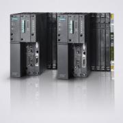
������S7-400CPU
-
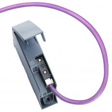
�����Ӵ�����
-
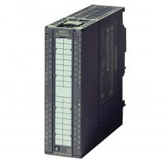
�����ӽ�����ģ��
-
������S7-300PLC
-
������ET200SP
-
������S7-200 SMART
-
������S7-1500CPU
-
�����ӱ�Ƶ��
-
������SITOP��Դ
-
������S7-200 CN
-
SIMATIC S7-1200PLC
-
�����ӵ�ѹ����
-
������G120
-
�����ӵ��ߵ���
-
�����ӵ��
-
�����Ӷ�ܲ����DZ�
-
������S7-200 SMART
-
������G120C
-
SINAMICS S120
-
��������������
-
SIMOTION D4x5-2���Ƶ�Ԫ
-
SENTRON 7KM PAC
-
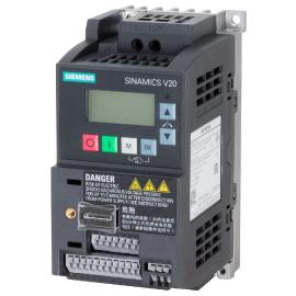
������V20��Ƶ��
-
�� ��